We are Hebei Leeter Import and Export Co., Ltd ("Leeter"), a wire, mesh, and masonry accessories manufacturer founded in 2006 in Dingzhou, Hebei, China. We supply masonry ties to contractors and distributors across North America and Europe, and we field spacing questions on nearly every project. This guide walks through how the rules work, where they tighten, and how to plan a layout that passes inspection.
Why codes use area per tie instead of a single spacing number
The core logic behind wall tie spacing is load sharing. A veneer wythe cannot resist wind or seismic pressure on its own, so it transfers that pressure back to the structural backup through the ties. Each tie carries the load from a tributary area of wall around it. Spread the ties too far apart and any single tie sees more force than it was tested for. That is why the code frames the rule as a maximum area per tie rather than one fixed dimension.
Think of it as a budget. If the code allows one tie per 2.67 square feet, you can distribute that area in different shapes. A grid at 16 inches vertical by 24 inches horizontal covers about 2.67 square feet per tie. A grid at 24 by 16 does the same. Both satisfy the area rule, but you still must respect the separate vertical and horizontal caps so no single dimension stretches too far even when the area math looks fine.
Here is a way we often explain it on site: the area rule protects against overload, and the maximum-spacing caps protect against buckling and bowing of the veneer between ties. You need both limits to hold at once. Meeting the area figure while blowing past a 16-inch vertical cap is not compliant, even if the arithmetic seems generous.
What are the baseline wall tie spacing limits?
Most modern projects in the United States anchor to TMS 402 (the Building Code Requirements for Masonry Structures) as referenced by the IBC. The widely cited baseline for adjustable ties is one tie per 2.67 square feet of wall area, with individual maxima commonly stated near 16 inches vertically and 32 inches horizontally. Wire ties and corrugated ties can carry different limits, so always match the value to the tie type you actually specify.
The table below summarizes the numbers we reference most often. Treat them as typical baseline values from the TMS 402 and IBC framework, not as a substitute for reading your adopted edition.
| Condition | Typical maximum area per tie | Typical spacing caps |
|---|---|---|
| Standard adjustable veneer tie | ~2.67 sq ft | ~16 in vertical, ~32 in horizontal |
| Corrugated sheet-metal tie (wood-frame backup) | ~2.67 sq ft | Often ~16 in vertical, ~24 in horizontal, plus tighter fastener rules |
| Around openings and at free edges | Extra ties required | Within ~12 in of the opening or edge |
| At movement/expansion joints | Extra ties on each side | Follow detail; do not span the joint |
Notice that the corrugated tie row is tighter on the horizontal dimension. Corrugated ties are thinner and more flexible, so codes and manufacturers frequently trim their allowable spacing. When you switch tie types mid-project, re-run the spacing rather than assuming the grid carries over.
Different tie systems, seismic categories, and wind speeds shift these figures. A stiff two-piece adjustable tie backed by a concrete masonry wall behaves very differently from a light corrugated strap on a wood-stud wall, and the code reflects that.
Where do you add extra ties around openings and edges?
Openings and free edges concentrate load, so codes require additional wall ties beyond the field spacing. A common requirement is extra ties spaced no more than about 24 inches apart around the full perimeter of every opening, positioned within roughly 12 inches of the opening. Free edges of the veneer, at parapets, control joints, and terminations, follow the same reinforcing logic.
The reasoning is physical. Wind pressure does not spread evenly across a wall. It piles up at corners, along the top edge, and around window and door heads and jambs. A veneer panel that is well tied in the field can still crack or pull loose at an untied edge. So the code treats perimeters as their own zone with denser anchoring.
We tell customers to plan opening ties before ordering, not after. The perimeter anchors around a run of windows can add a meaningful count of ties to a job, and missing them is one of the most common reasons a masonry inspection gets flagged. Map the openings, walk the perimeter of each, and place ties within the 12-inch band on all four sides, including the sill.
Parapets deserve special attention because they are exposed to wind on both faces and often sit above the roof line with no return support. Many details call for tighter tie spacing through the parapet and a robust connection at the top course. Check the parapet detail separately from the field wall.
How does seismic and high-wind design tighten spacing?
Seismic design categories and high-wind regions push wall tie spacing well below the baseline. In higher seismic categories, TMS 402 provisions reduce the maximum area per tie and often require prescribed joint reinforcement connected to the ties. In coastal high-wind zones, design wind pressures can double or more, and the tributary area each tie handles must shrink to match. A layout that passes in a low-hazard inland site may be non-compliant on the coast.
The mechanism is the same load-sharing math, run with a bigger number. If wind pressure rises, either each tie must be stronger or you place more of them to cut the tributary area. Since most standard ties have a fixed tested capacity, the practical answer is usually more ties, closer together. We routinely see coastal specifications call for area-per-tie figures noticeably below the 2.67 square-foot baseline, along with continuous horizontal joint reinforcement.
Seismic detailing adds another layer. Beyond spacing, higher seismic categories may require that ties engage bed-joint reinforcement so the veneer acts more as a unified panel, and they may restrict certain corrugated ties entirely. Do not carry a corrugated-strap detail from a low-seismic job into a high-seismic one without checking whether it is still permitted.
Two practical habits help here. First, read the structural drawings, not just the architectural elevations, because the wind and seismic pressures live in the structural set. Second, when the project spans multiple exposure zones, spacing may vary across the same building, so label the zones clearly on the shop drawings.
How do you turn the rules into a real tie layout?
Start with the governing area per tie from your adopted code and the project's wind and seismic data, then convert it into a grid that also respects the vertical and horizontal caps. A quick method: pick your course-based vertical spacing first, since ties usually land in bed joints, then solve for the horizontal spacing that keeps the area at or below the limit. Verify the result against both maximum caps, then add perimeter and edge ties.
A worked example makes it concrete. Suppose the code gives 2.67 square feet per tie and you want ties every 16 inches vertically to match the brick coursing. Divide 2.67 square feet (384 square inches) by 16 inches, and you get 24 inches horizontal. That grid, 16 by 24, satisfies the area rule and sits under the 32-inch horizontal cap. If the coursing pushed vertical spacing to 24 inches, the horizontal figure would drop to 16 inches to hold the same area.
We recommend three checks before the ties get ordered. Confirm the tie type matches the backup and cavity width. Confirm the layout respects the tighter of the area rule and the two spacing caps. Confirm the opening, edge, and joint ties are counted separately and added on top of the field grid. Miss the last step and the field count will look right while the wall stays under-tied where it matters most.
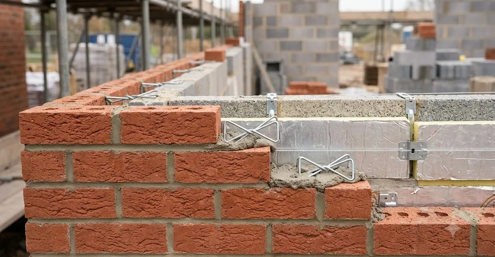
Cavity width and tie embedment matter too. A tie must have adequate embedment in the mortar bed and cannot be over-bent to reach across an oversized cavity. If the cavity grows because of thicker insulation, verify the tie is rated for that reach before assuming the old spacing still applies. Our brick wall ties come in adjustable and fixed styles for a range of cavity widths, and we are glad to match a tie to a specified spacing if you request a quote.
Common wall tie spacing mistakes we see
The most frequent error is treating the area rule and the spacing caps as interchangeable. They are not. You must satisfy whichever is more restrictive for your geometry. A wall with tall coursing can meet the area figure yet still violate a horizontal cap, or the reverse. Run both checks every time rather than trusting a single number that worked on a past job.
A second recurring mistake is forgetting the perimeter and edge ties. Field spacing gets the attention because it covers the largest area, but inspectors look hard at openings, corners, parapets, and terminations. These zones fail more often than the field.
A third issue is stale details. Codes update on a cycle, and a spacing detail copied from a five-year-old project may reference a superseded edition. Confirm the adopted edition at the start, because a jurisdiction may enforce a different version than the one you used last year in another county.
Frequently asked questions
What is the maximum wall tie spacing allowed by code?
A common baseline from TMS 402 and the IBC is one tie per 2.67 square feet of wall, with maxima near 16 inches vertically and 32 inches horizontally for standard adjustable ties. These are typical values, not universal ones. Seismic category, wind speed, and tie type can lower them, so confirm your adopted edition.
How many wall ties do I need per square foot?
If the code allows one tie per 2.67 square feet, you need roughly 0.375 ties per square foot, or about 3 to 4 ties per 10 square feet of field wall. Add perimeter ties around every opening and along free edges on top of that field count, since those anchors are required separately from the field grid.
Do wall ties need to be closer together around windows and doors?
Yes. Codes require additional ties around the full perimeter of openings, commonly spaced no more than about 24 inches apart and placed within roughly 12 inches of the opening. This applies to all four sides, including the sill. The same denser anchoring logic covers corners, parapets, control joints, and other free edges of the veneer.
Does wall tie spacing change in high-wind or seismic zones?
It does. Higher design wind pressures and higher seismic design categories reduce the allowable area per tie, so ties move closer together and often connect to continuous joint reinforcement. Some corrugated ties may not be permitted in higher seismic categories. Always read the structural drawings, since the governing wind and seismic pressures are specified there.
Which code governs masonry wall tie spacing in the United States?
Most U.S. projects follow TMS 402, the Building Code Requirements for Masonry Structures, as referenced by the International Building Code. Your local jurisdiction adopts a specific edition and may add amendments. Confirm the exact edition and any local changes before finalizing a layout, because spacing values and language differ between editions.
Talk to us about your spacing plan
Wall tie spacing looks simple once you separate the area rule from the caps and remember the perimeter anchors, but the right tie for your cavity and backup still matters. If you want help matching a tie to a specified layout, or you need a quote on adjustable, fixed, or corrugated ties for a North American or European project, contact our team and we will follow up promptly.
