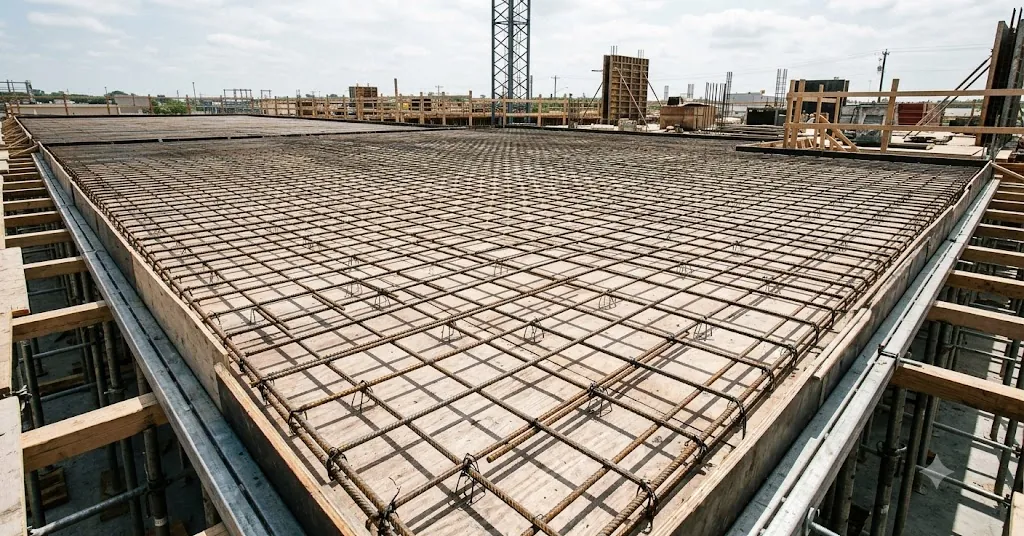
At Leeter, we manufacture wire, mesh, and the rebar chairs that hold steel in position, so we see the same placement questions come up on jobsites across North America and Europe. We started exporting from Dingzhou, Hebei in 2006, and the recurring theme is simple: placement problems almost always trace back to skipping a step, not to a lack of material. This guide walks through how to read the drawings, set spacing, hold cover, tie, lap, and inspect.
One point before we start. This guide covers placement, the field work of putting bars where the design says they go. It does not cover structural design. Bar sizes, quantities, spacing values, cover requirements, and lap lengths all come from the engineer of record and the project drawings. When the field and the drawing disagree, you stop and ask. You never guess.
Reading the placing drawing
The placing drawing is your instruction sheet, and it tells you far more than most crews use. Before any steel goes down, read it fully. A placing drawing, sometimes called a placement or shop drawing, translates the engineer's structural design into a bar-by-bar layout that a crew can build from. It shows what goes where, how much, and in what order.
Every placing drawing carries a bar schedule. This table lists each bar mark, the bar size, the shape, the cut length, the bend dimensions, and the quantity. The bar mark is the key. When a drawing calls for "12 of mark 4A at the north footing," you find bundle 4A, confirm the tag, and place twelve. Matching tags to marks is the single fastest way to avoid placing the wrong steel.
Read the notes block too. General notes usually state the concrete cover for each element, the lap splice class, the tie requirements, and any special instructions such as epoxy-coated bar handling. These notes override assumptions. If the note says 2 inches of cover on a footing and 1.5 inches on a wall, that difference changes which chairs you pull from the pile.
Section views matter as much as plan views. A plan shows spacing across the element; a section shows which mat sits on top, how bars hook at edges, and where the cover falls. Reading only the plan is how top bars end up on the bottom. Check both, every time, and orient the drawing to match how you are standing on the pour.
Getting spacing right
Spacing controls how load moves through the concrete, so it is not a place for eyeballing. The placing drawing gives a center-to-center dimension, for example bars at 12 inches on center. That number is measured from the middle of one bar to the middle of the next, not edge to edge, and it applies across the full run.
Mark your spacing before you place. Chalk lines, a spacing template, or a marked screed board all work, and all beat measuring bar by bar. On a slab, snap lines both directions and lay bars to the marks. Consistent spacing reads instantly on inspection and prevents the slow drift that leaves you short a bar at the far end.
Watch the ends and edges. Most drawings dimension the first bar off the form face, often at half the spacing or at a set clearance. Get that first bar right and the rest follow. If a run does not divide evenly, the drawing or the engineer decides where the odd space goes, not the crew. Do not silently widen the last gap to make the math work.
Openings, blockouts, and penetrations interrupt spacing, and the drawing shows added trim bars around them. These extra bars carry load around the hole. Place them exactly as detailed. Skipping trim steel because "it looks fine" is a common field shortcut that later shows up as cracking at the corner of an opening.
Holding cover with chairs and supports
Concrete cover is the clear distance between the bar and the concrete surface, and it protects the steel from corrosion and fire. This is where supports earn their place. Cover is set almost entirely by the chairs, bolsters, and spacers that hold bars off the form and off the ground.
| Support type | Typical use | Holds bars |
|---|---|---|
| Individual bar chair | Slabs on grade, top and bottom mats | At a set height above the form |
| Slab bolster | Continuous support for bottom mat | Along a full line of bars |
| Wire high chair | Upper mat in thick slabs and decks | At taller, specified heights |
| Beam bolster | Beams and grade beams | Bottom bars off the form |
| Wheel spacer | Walls and columns | Side cover against vertical forms |
Pick the support height from the required cover, not from habit. If a slab calls for 1.5 inches of bottom cover, the chair must hold the bar at 1.5 inches, measured to the underside of the steel. Mixing chair heights in one mat gives you a wavy bar layout and inconsistent cover, which an inspector will flag.
Space the supports closely enough that bars do not sag between them. A common failure is setting chairs too far apart, then watching the mat dip when workers walk on it during the pour. Support spacing depends on bar size and mat weight, so follow the placing drawing or the support manufacturer's guidance, and add chairs before the pour rather than after the sag shows.
On the ground, the base matters. A chair on soft soil punches through and loses cover. On grade or on a vapor barrier, use supports with a wide foot or a sand plate so they stay put under load. Getting cover right at the top of the pour means nothing if the bottom bar is sitting in the mud.
Tying reinforcement securely
Ties do not add strength, but they keep the whole assembly where you placed it, which is the entire point of placement. A tie holds intersecting bars together so spacing and cover survive the concrete placement. The concrete does the structural work; the ties just make sure the steel is still in position when the concrete arrives.
Use the right rebar tie wire and the right tie for the situation. Annealed steel tie wire, commonly 16 or 16.5 gauge, is the workhorse for hand tying and for battery-powered tie tools. Softer annealed wire twists tighter and snaps less. The tie pattern comes from the drawing or the general notes, so read them before assuming every intersection needs a tie.
You rarely tie every crossing. On a typical slab mat, tying every intersection wastes wire and time. Many details call for tying every second or third intersection in a staggered pattern, which holds the mat rigid enough to walk and pour on. Perimeter bars, corners, and lap splices usually do get tied at each point because that is where the mat wants to spread.
The snap tie, the saddle tie, and the wrap-and-saddle tie each suit a different joint. A simple snap tie holds flat slab crossings. A saddle tie grips harder for walls and columns where bars must not shift under vibration. Match the tie to the load the joint will see during placement, and keep tie ends turned down into the concrete, away from the cover face, so they do not rust and stain the surface.
Laps and splices
Bars come in finite lengths, so laps are how continuous reinforcement gets built across a long run. A lap splice overlaps two bars so load transfers from one to the other through the concrete. The lap length and location come from the engineer and the placing drawing, never from a field estimate, because lap length depends on bar size, concrete strength, and bar position.
Place laps where the drawing shows them. Splices are usually located away from points of maximum stress, and the drawing marks those zones. Moving a lap to a convenient spot because the bar ran short can put the splice in the wrong place. If a bar falls short of the detailed lap, you call the drawing, not your own judgment.
Stagger laps when the detail requires it. Bunching every splice at the same cross-section creates a weak line, so many details stagger adjacent laps along the run. Lap the bars in full contact, tie them firmly at the ends and middle, and keep the lapped pair inside the cover envelope so the splice does not crowd the surface.
Inspection checkpoints before the pour
The pre-pour inspection is the last chance to catch a placement error before concrete hides it forever. Walk the whole placement against the drawing before anyone calls the truck. A structured pre-pour walk, ideally with the drawing in hand, catches the errors that are cheap to fix now and expensive to fix later.
| Checkpoint | What to confirm |
|---|---|
| Bar marks and count | Every mark matches the schedule and quantity |
| Spacing | Center-to-center matches the drawing both ways |
| Cover | Chairs hold correct clearance top, bottom, sides |
| Ties | Pattern and count hold the mat rigid |
| Laps | Length, location, and stagger match the detail |
| Trim steel | Added bars present at openings and corners |
| Cleanliness | Bars free of mud, oil, loose rust, ice |
Confirm the mat cannot move. Push on it, walk it, and see whether it sags or shifts. If it moves under a boot, it will move under a concrete hose and vibrator. Add chairs and ties until the assembly is stiff. A mat that holds its position through the pour is the whole goal of everything above.
Document the checkpoint. A quick set of photos and a signed pre-pour checklist protect the crew and give the inspector confidence. Many projects require third-party or engineer sign-off before concrete arrives, so build that hold point into the schedule rather than treating it as a surprise. The pour waits for the inspection, not the other way around.
Frequently asked questions
What is the difference between rebar detailing and rebar placement?
Detailing is the office work of turning the engineer's design into placing drawings and bar schedules that specify every bar mark, shape, and length. Placement is the field work of installing those bars on chairs at the right spacing, cover, tie, and lap. Detailing tells the crew what to build; placement is building it.
How do I know what concrete cover to use?
The required cover comes from the placing drawing's general notes and the project specification, set by the engineer for each element. Footings, walls, slabs, and columns often carry different values. Read the notes, then choose chair and spacer heights that hold the bar at exactly that clearance. Never assume a single cover applies everywhere on a job.
Do I need to tie every rebar intersection?
Usually not. Tying every crossing wastes wire and time without adding structural value, since ties only hold bars in position during the pour. Most details call for a staggered pattern, often every second or third intersection, with perimeters, corners, and laps tied at each point. Follow the tie pattern shown on the drawing.
Where should rebar laps be located?
The engineer and placing drawing set lap location, length, and stagger. Splices generally sit away from points of maximum stress, in zones the drawing marks. If a bar runs short of a detailed lap, stop and check the drawing rather than relocating the splice. Field-moved laps in the wrong zone can weaken the member.
What should a pre-pour rebar inspection cover?
Check bar marks and counts against the schedule, spacing both directions, cover at top, bottom, and sides, tie pattern, lap length and location, and trim steel at openings. Confirm the mat stays rigid when walked. Bars should be clean of mud, oil, and loose rust. Document the walk with photos and a signed checklist.
Placement is a discipline of following the drawing, holding position, and checking your work before the concrete arrives. Get the marks, spacing, cover, ties, and laps right, and the reinforcement does its job for the life of the structure. If you need tie wire, chairs, or mesh sized to your placing drawings, request a quote and our team will help you match materials to the job.
